The Stirling engine

Caner Türkmen
08. June 2021
08. June 2021
A Swiss high school student was required to build something for his final project. As so many Stirling engine kits are available, the devices are expected to be important to our future, and he wanted to learn more about this type of engine, he decided to focus on creating one of his own.
But to make it a reality, he needed a sensor that would work at high temperatures (approx. 100 °C). The sampling rate also needed to have as high a frequency as possible (at least 100 Hz). KELLER Pressure provided him with an M5HB on the condition that he give the company an insight into his work once complete. A summary of the topic:
Named after its creator Robert Stirling, the Stirling engine was invented in 1816. However, it was not until much later that the engine came into mainstream use as its production was too complex and it required a high degree of precision to manufacture.
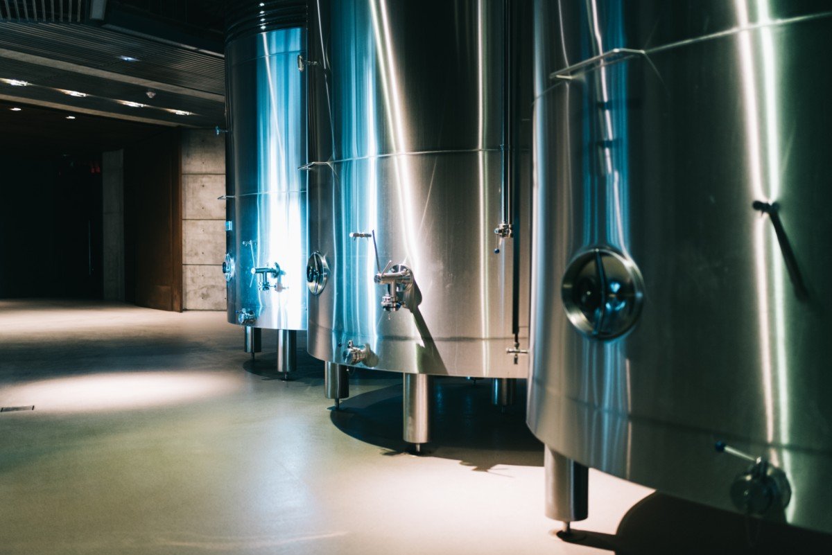
By around 50 years ago, things had changed. Manufacturing precision had improved considerably, and as the Stirling engine does not produce environmentally harmful exhaust fumes, it has now become a more attractive option and demand has grown accordingly. No combustion process takes place inside the engine. Instead, it continually reuses the same gas, which circulates in a completely sealed space/container. The heat expansion and cooling compression of the gas moves the motor.
The Stirling engine is also used as a cooling unit or heat/water pump for solar energy generation on satellites and submarines.
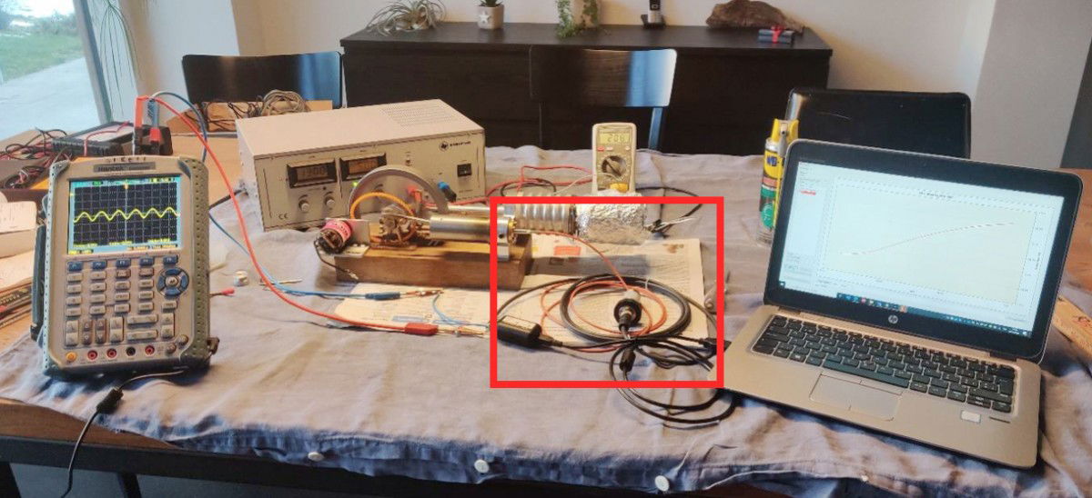
In the student’s project, the M5HB ultra-fast high-temperature pressure transmitter (see image, marked in red) was used to measure pressure and monitor the temperature. With the aid of a K-114 converter and the Control Center Series 30 (CCS30) software, he used it to create a temperature curve and measure and verify the pressure range.
How does a Stirling engine work?
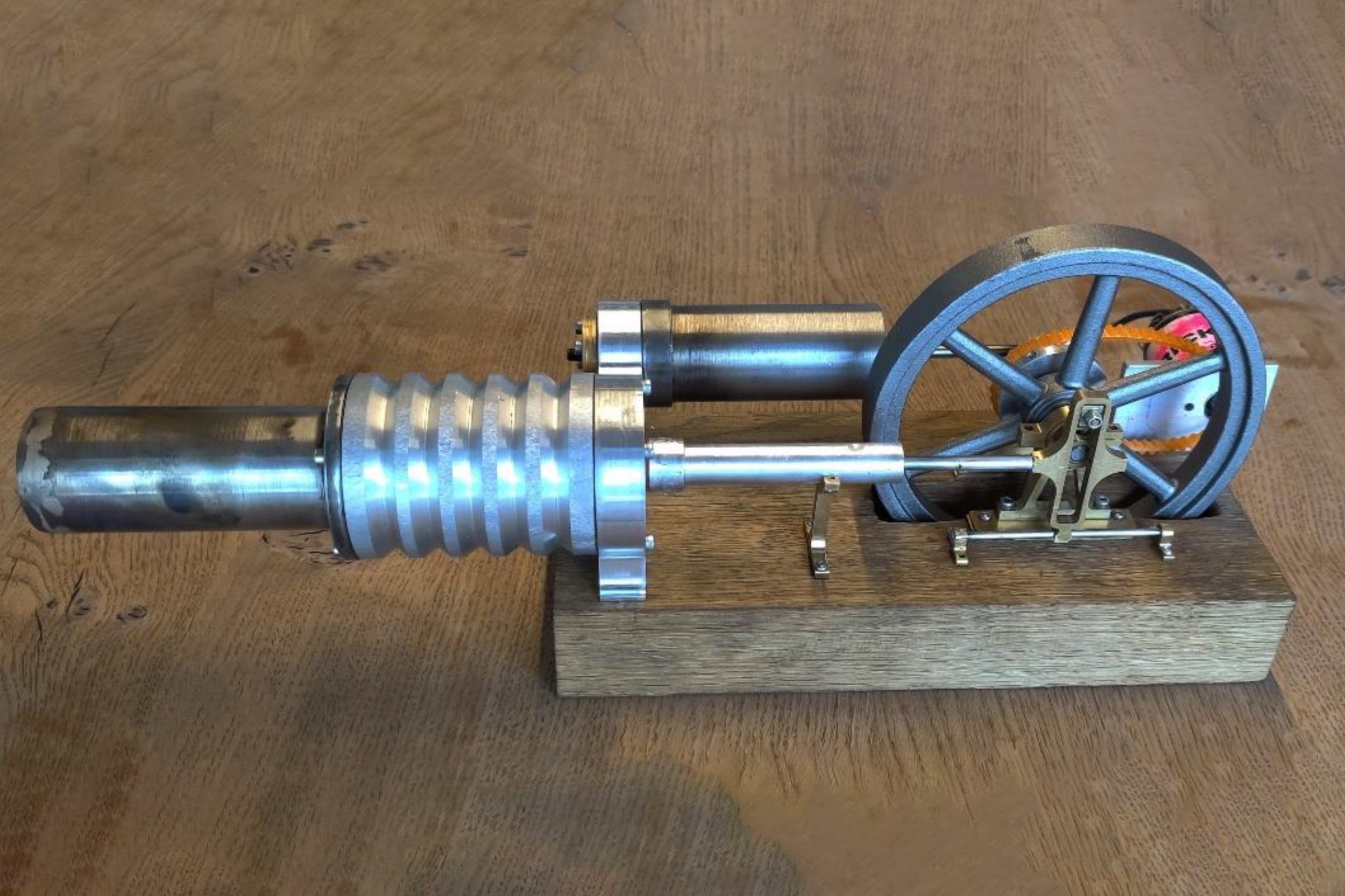
The engine contains two cylinders, with one always warmer than the other. The gas is heated and expands in the warm cylinder, while in the cold one, it is cooled and compressed. The cylinders are connected to one another via a heat exchanger that allows a gas exchange to take place. The warm cylinder contains substantially more gas than the cold one. This means that the piston in the warm part pushes outwards. This in turn sets the flywheel in motion. As the piston from the warm cylinder pushes outwards, it draws out the one in the cold cylinder too.
The following YouTube video explains the Stirling engine in a simple, clear way:
https://www.youtube.com/watch?v=c95iGtgUDhU
The student’s construction of the Stirling engine was successful, his project fascinating, and the insights gained from it valuable.
Share
«Possible applications for the Stirling engine include cooling units and heat / water pumps.»
Caner Türkmen
Commercial Apprentice